Product Catalog
Industrial & Railway Grade Converter Solutions
High-density board-mount modules, encapsulated isolated converters, and ruggedized vehicle-grade charging systems optimized for rolling stock, commercial transport, and heavy equipment.
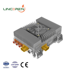
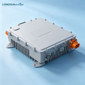
Premium IP67 Waterproof & Air-Cooled Bidirectional 3.3 KW OBC & 1.8 KW DCDC Converter 2-in-1 Assembly for EV
Get a Quote
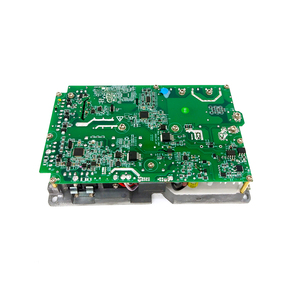
Dilong 3.3kW OBC EV On-board Charger Module 100V-200V Output DA3K3M13-150C Models
Get a Quote
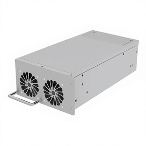
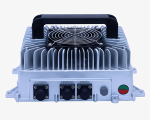
High Efficiency AC to DC Fast Charger 3.3kW Power Supply Rack-Mounted AC/DC OBC Module
Get a Quote
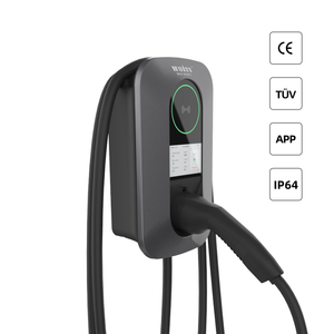
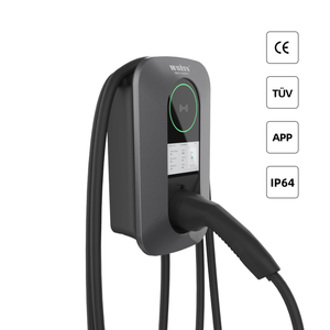
3.3kw Obc Charger Module New 2kw Wall-mounted Ev Charging Station 48v 72v 144v Smart Pile
Get a Quote
Industrial Grade 3.3KW EV Charger Module OBC DC DC Integrated Charger IP67 Waterproof
Get a Quote
3.3kw Ev On Board OBC Charger 48V 60V 72V 84V 96V 120V 144V 312V Battery Charger with CAN BUS
Get a Quote
3.3KW OBC DC Charger Module New 2KW Wall-Mounted EV Charging Station 48V 72V 144V Floor Mounted
Get a Quote
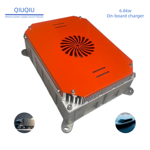
3.3kw EV OBC DC Charger Module 6.6kw OBC 48V 72V 144V Lithium LiFePO4 Battery Charger
Get a Quote
96.5%
Peak Conversion Efficiency
14.4V - 168V
EN 50155 Ultra-Wide Input
3000 VAC
Reinforced Galvanic Isolation
>1.5M Hrs
Demonstrated Field MTBF
Engineering Excellence in Railway Power Conversion: Architectural Standards & Field-Proven Reliability
Modern railway rolling stock—ranging from high-speed passenger trains (HST) and heavy-haul freight locomotives to light rail transit (LRT) and metro systems—demands uninterrupted auxiliary electrical power under severe environmental and electrical stress. Power conversion systems deployed in these rail environments serve as the critical spine for train control and monitoring systems (TCMS), door control units, braking systems, HVAC controls, signaling equipment, passenger infotainment, and emergency battery backup charging networks.
As a leading OEM/ODM Railway Converter Manufacturer & Exporter, our engineering design principles prioritize total system robustness, compliance with international rail standards, and high power density. Railway electrical grids are inherently harsh: supply lines experience continuous voltage fluctuations, high-amplitude inductive spikes, power interruptions, extreme ambient temperature variations (-40°C to +85°C), high humidity, mechanical shock, and persistent vibration. Meeting these demands requires custom power module topology selection, advanced magnetic design, and rugged thermal management.
Key Design Compliance Standard: EN 50155 (Railway Applications – Rolling Stock Electrical Equipment) specifies that power supplies must maintain regulated outputs through input voltage dips down to 0.60 Un for 100ms and voltage surges up to 1.40 Un for 1 second, with zero interruption in system operation.
Nominal Input Voltages and Continuous Operating Ranges
Global rail transportation systems operate across diverse nominal DC battery voltages. OEM/ODM converters must accommodate standard nominal inputs of 24VDC, 48VDC, 72VDC, 96VDC, and 110VDC. To eliminate the need for multi-sku inventories, modern rail architectures utilize ultra-wide 4:1 and 10:1 input ranges. An continuous input window spanning 14.4 VDC to 168 VDC allows a single standard quarter-brick or half-brick converter module to operate seamlessly across virtually all standard railway supply lines worldwide.
EN 50155 & RIA 12 Immunity
Integrated active surge protection circuits withstand 3.5 Un surges up to 20ms according to UK RIA 12 specifications without component degradation.
Wide Bandgap Semiconductors
Silicon Carbide (SiC) MOSFET switching topologies reduce thermal losses by 40% and boost switching frequencies, drastically minimizing transformer footprint.
Reinforced Isolation (3kVAC)
High creepage and clearance PCB layouts deliver 3000 VAC input-to-output and 1500 VAC input-to-case isolation, safeguarding downstream microelectronics.
Thermal Dissipation & Structural Encapsulation Techniques
Thermal stress is the primary failure driver in power semiconductor assemblies. Our board-mounted and chassis-mounted DC-DC converters utilize full polyurethane or silicone potting encapsulation within aluminum enclosure designs. Vacuum potting removes micro-air voids, achieving superior dielectric breakdown resistance and optimal thermal conduction from internal switching elements (MOSFETs, planar transformers, output diodes) to the cold plate baseplate. Conduction cooling via metal baseplates enables fanless operation, preventing conductive dust, moisture, and metallic grinding debris from infiltrating the converter circuit.
Global Procurement Trends & Future Technological Trajectories
The global market for railway traction converters, auxiliary power converters (APC), and board-mounted isolated DC-DC modules is undergoing a structural transition driven by decarbonization mandates, network electrification, catenary-free light rail systems, and autonomous train operation (ATO). B2B procurement managers and system integrators must align their sourcing strategies with several key technological shifts expected over the next decade:
1. Shift to Wide Bandgap (WBG) Semiconductors: SiC & GaN Dominance
Traditional silicon (Si) IGBTs and MOSFETs are rapidly reaching their physical thermal and switching speed limitations. Next-generation railway DC-DC converters and EV on-board chargers (OBC) increasingly feature Silicon Carbide (SiC) power switches and Gallium Nitride (GaN) HEMTs. SiC technology enables operation at higher switching frequencies (above 100 kHz to 500 kHz), reducing the physical size of inductors and planar transformers by up to 60%. This shift achieves system-level efficiencies exceeding 96.5%, dramatically paring down parasitic heat generation and overall energy consumption in passenger cars.
2. Universal Standardization via DOSA and Open-Frame/Encapsulated Bricks
Rail operators and Tier-1 integrators are moving away from proprietary, single-source power supplies toward standardized physical footprints. Distributed Power Architectures (DPA) relying on DOSA (Distributed-power Open Standards Alliance) pinouts—such as 1/16th brick, 1/8th brick, quarter brick, half brick, and full brick modules—allow procurement departments to mitigate supply chain risks. OEM buyers can source form-, fit-, and function-compatible drop-in replacements, maintaining continuity of supply for 15-to-25-year locomotive lifespan commitments.
3. Convergence of Railway Auxiliary Power and E-Mobility Ecosystems
The technology crossover between electric commercial vehicles (e-busses, electric trucks, mining haulers) and light rail vehicles is accelerating. High-voltage to low-voltage (HV-to-LV) isolated DC-DC converters originally optimized for 400V/800V EV traction battery packs are now being re-engineered for railway battery-buffered auxiliary grids. Features like bidirectional power flow (V2G/V2X capable), integrated IP67 liquid/air-cooling plates, and CAN bus (CANopen / J1939) diagnostic interfaces are becoming standard procurement requirements across both sectors.
4. Stringent Fire & Smoke Standards: EN 45545-2 (HL3 Rating)
Safety regulations across Europe, Asia, and North America mandate full compliance with fire protection standard EN 45545-2 for all interior and exterior rolling stock components. Future-proof procurement requires converters constructed exclusively from certified low-smoke, non-toxic, self-extinguishing materials achieving Hazard Level 3 (HL3) under test requirements R22 and R23. Potting compounds, PCB substrates, and plastic headers must pass rigorous flammability and oxygen index testing to ensure passenger safety in underground tunnel operations.
Enterprise OEM/ODM Engineering & Customization Roadmap
As an established enterprise OEM/ODM manufacturer, NetPower Technologies and our specialized manufacturing facilities provide comprehensive design, prototyping, and volume manufacturing services tailored to international train builders, system integrators, and industrial power users. We bridge the gap between off-the-shelf standard power bricks and complex, application-specific power conversion assemblies.
End-to-End Customization Workflow
- System Specification & Topology Selection: Our power engineering team evaluates input voltage swing, peak transient exposure, ripple/noise requirements, and thermal constraints to choose the ideal topology—Phase-Shifted Full-Bridge (PSFB), Active-Clamp Forward, or LLC Resonant converter.
- Mechanical & Thermal Packaging: Custom enclosure sizing, connector integration (M12 rail-rated connectors, terminal blocks, or heavy-duty busbars), baseplate geometry, and IP67/IP68 sealing design.
- Firmware & Digital Control Integration: Development of custom CANbus, MODBUS, or PMBus communications protocols for real-time telemetry, telemetry reporting, temperature monitoring, output trim, and dynamic fault logging.
- Design Verification & Pre-Compliance Testing: In-house environmental chambers subjected to HALT/HASS, thermal shock (-55°C to +125°C), thermal cycling under full electrical load, and conducted/radiated EMI profiling in anechoic chambers.
Quality Assurance Commitment: Every single production unit undergoes 100% automated optical inspection (AOI), 100% in-circuit testing (ICT), high-voltage isolation flash testing, and full-load burn-in under dynamic thermal cycling prior to dispatch.
Robust Field Reliability & Compliance Matrix
Our manufacturing protocols adhere strictly to ISO 9001 and IATF 16949 quality management systems. Product lines intended for rail and e-mobility undergo exhaustive third-party laboratory verification to obtain full certification against international transport benchmarks:
- EN 50155 / IEC 60571: Rolling stock electronic equipment compliance.
- IEC 61373: Shock and vibration testing (Category 1, Class B body-mounted and Class A bogie-mounted).
- EN 50121-3-2: Electromagnetic compatibility (EMC) for rolling stock apparatus.
- EN 45545-2: Fire safety compliance for railway components (HL1 to HL3).
- UL 62368-1 / EN 62368-1: International safety standards for audio/video, information, and communication technology equipment.
Frequently Asked Questions (FAQ) for Procurement & Power Engineering
This technical FAQ addresses common challenges, design parameters, and compliance queries raised by industrial buyers, power system designers, and global procurement teams when selecting railway DC-DC converters and vehicle charger modules.
What specific input voltage ranges are required for EN 50155 railway power supplies?
EN 50155 defines several standard nominal voltages for train battery supplies: 24V, 48V, 72V, 96V, and 110V DC. A compliant converter must operate continuously from 0.70 to 1.25 times the nominal voltage, handle dips to 0.60 Un for 100ms, and withstand surges up to 1.40 Un for 1 second. Ultra-wide input converters (such as 14.4V–168V DC input) cover all standard nominal voltages within a single module, simplifying procurement and logistics.
How do ultra-wide 10:1 input DC-DC converters benefit OEM rail system designers?
An ultra-wide 10:1 input range (e.g., 14.4V to 168V DC continuous) enables a single standardized DC-DC power converter module to be deployed across global rail fleets regardless of local nominal line voltages (24V in light rail, 72V/110V in heavy rail passenger cars). This minimizes stocking SKUs, lowers engineering design costs across multiple vehicle platforms, and simplifies inventory management for long-term maintenance contracts.
What is the distinction between conduction cooling, forced-air cooling, and liquid cooling in high-power converters?
Conduction cooling transfers heat directly from internal high-power components through an aluminum baseplate into a vehicle chassis or external heatsink, enabling fanless sealed IP67 enclosures immune to dust and moisture. Forced-air cooling uses integrated fans to draw ambient air over heatsink fins, suitable for ventilated equipment racks. Liquid cooling circulates coolant (water/glycol) through an internal cold plate, ideal for high-power density converters (3kW to 20kW+) where space is extremely constrained.
How is hold-up time managed during power supply interruptions on rolling stock?
EN 50155 specifies hold-up time classes S1 (no interruption), S2 (10ms interruption), and S3 (20ms interruption). During switching between power supply zones or pantograph bounce, input voltage drops to zero. Railway converters incorporate internal high-voltage electrolytic capacitor banks or active hold-up circuits to store energy and maintain full regulated output during these micro-interruptions without resetting downstream electronics.
What MTBF calculation models are utilized, and how is long-term field reliability guaranteed?
Mean Time Between Failures (MTBF) is calculated in accordance with Telcordia SR-332 (Issue 4) or MIL-HDBK-217F standards at an ambient reference temperature of +40°C. Our railway converters achieve field-proven MTBF ratings exceeding 1,500,000 hours. Reliability is assured through conservative component de-rating (derating stress factors below 50% for voltage and current), high-grade 125°C long-life capacitors, thermal modeling, and 100% dynamic load stress screening.
Can NetPower support custom mechanical enclosures, pinouts, and custom CANbus interfaces?
Yes. Our OEM/ODM engineering teams specialize in custom mechanical retrofits, tailor-made mounting plates, custom wiring harness integrations, and non-standard pin configurations to meet existing legacy system footprints. Additionally, we provide custom software firmware for CANopen, J1939, or Modbus protocols to support real-time telematics, fault reporting, and remote diagnostic monitoring.
What level of isolation is standard for railway traction and auxiliary power converters?
Standard railway power converters feature reinforced galvanic isolation ranging from 1,500 VAC up to 3,000 VAC (or 4,200 VDC) between input circuits and output logic, and 1,500 VAC between input and metal case enclosure. High isolation prevents high-voltage supply surges on the primary catenary/battery line from damaging sensitive 5V, 12V, or 24V digital control electronics.
What is the typical lead time and sample availability for customized OEM/ODM projects?
Standard product evaluation samples ship within 3 to 5 business days. Semi-custom modifications (such as voltage trimming, custom pin lengths, or firmware tweaks) typically take 2 to 4 weeks. Full custom OEM ground-up developments—from initial schematic design to EVT/DVT prototype testing and pre-compliance certification—generally range from 8 to 14 weeks depending on mechanical complexity.
Ready to Engineer Your Custom Railway or E-Mobility Power Solution?
Consult directly with our application engineers for topology optimization, thermal simulation support, sample requests, and global volume pricing.