
Engineered for extreme reliability, grid code compliance, and seamless multi-megawatt scalability across global renewable energy, industrial power, and energy storage architectures.
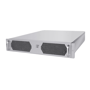
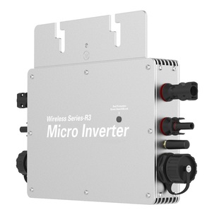
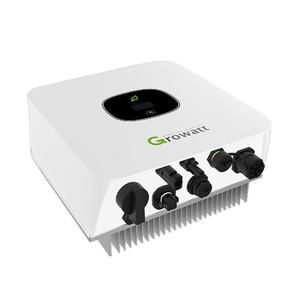
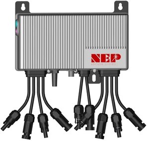
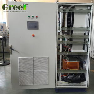
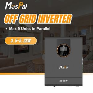
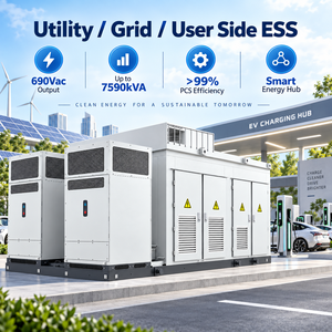
The global transition toward decentralized renewable energy, utility-scale Battery Energy Storage Systems (BESS), and green microgrid networks has transformed grid power electronics from localized power conditioning units into critical utility grid anchors. As electrical grids face escalating integration of intermittent renewable energy sources, procurement officers, EPC contractors, and system integrators face stringent performance, safety, and interoperability mandates. Selecting accredited CE Certified Grid Converter Factories & Suppliers is no longer merely a regulatory formality; it is a foundational risk-mitigation strategy for multi-million-dollar energy projects.
CE marking signifies strict adherence to European Union safety, health, and environmental protection standards—specifically the Low Voltage Directive (LVD 2014/35/EU), Electromagnetic Compatibility (EMC Directive 2014/30/EU), and Radio Equipment Directive (RED 2014/53/EU). In utility and commercial applications, grid converters must simultaneously comply with modern grid codes such as EN 50549-1/2, VDE-AR-N 4110/4120, and IEC 62109-1/-2. Procurement teams must look beyond superficial pricing and evaluate factories based on their fundamental topology research, wide-bandgap (SiC/GaN) semiconductor integration, automated production testing, and documented information gain across lifetime performance metrics.
The technical evolution of grid-connected power electronics is defined by the shift from traditional Grid-Following (GFL) inverters to advanced Grid-Forming (GFM) bidirectional power converters. Understanding this topological divergence is paramount when sourcing grid equipment for microgrids, islanded networks, or high-penetration renewable grids.
Grid-following converters treat the utility grid as an ideal, infinite voltage source. Using Phase-Locked Loops (PLL), a GFL inverter tracks the grid voltage vector angle and injects synchronized sinusoidal currents. While highly efficient under stiff grid conditions, GFL systems suffer from severe instability, phase-slip, and control degradation when operating in weak grids characterized by low Short-Circuit Ratios (SCR < 2.0).
Grid-forming converters, such as utility-scale BESS PCS units (ranging from 30kW up to 6900kW platforms), operate as voltage sources behind an internal virtual impedance. Rather than relying on a PLL for synchronization, GFM converters establish voltage magnitude and frequency independently. They provide instantaneous voltage support, black-start capabilities, and synthetic inertia during sudden load variations or generator trips.
| Technical Characteristic | Grid-Following (GFL) Converter | Grid-Forming (GFM) Converter |
|---|---|---|
| Primary Operating Mode | Controlled Current Source | Controlled Voltage Source |
| Grid Synchronization Mechanism | Phase-Locked Loop (PLL) | Virtual Synchronous Machine (VSM) / Droop |
| Weak Grid Stability (SCR < 1.5) | Prone to Control Instability / Trip | Inherently Stable & Self-Sustaining |
| Black Start Capability | No (Requires External Voltage Grid) | Yes (Can Re-energize Dead Grids) |
| Harmonic Mitigation (THD) | Active Filtering Dependent | Native Voltage Source Filtering |
The integration of Silicon Carbide (SiC) MOSFETs and Gallium Nitride (GaN) high-electron-mobility transistors has revolutionized power density metrics in CE certified grid converters. Legacy IGBT-based converters were constrained by switching frequencies below 10 kHz, forcing manufacturers to utilize bulky magnetic transformers and massive passive LCL filters.
By transitioning to 1200V and 1700V SiC power modules, Tier-1 manufacturing facilities achieve switching frequencies between 40 kHz and 100 kHz. This yields three transformative advantages:
High switching speeds reduce passive magnetic component volumes by up to 60%, allowing compact 1/32nd to Full-Brick modules or smaller outdoor IP67 micro-inverter enclosures.
SiC switching losses are up to 80% lower than legacy silicon IGBTs, elevating full-load converter efficiency beyond 98.8% and reducing cooling auxiliary power overhead.
Lower operating junction temperatures ($T_j < 125^\circ\text{C}$) significantly slow thermal degradation in gate drivers and DC-link film capacitors, ensuring a 25-year service life.
Evaluating factory capability requires rigorous auditing of quality management systems. Leading CE certified grid converter suppliers implement automated manufacturing execution systems (MES) coupled with full material traceability down to individual MOSFET wafer lots.
Before leaving the manufacturing line, every grid converter undergo a series of stress-screening protocols designed to eliminate infant mortality failures:
A legitimate CE certified grid converter must demonstrate compliance with the European Low Voltage Directive (LVD 2014/35/EU) via safety standard IEC/EN 62109-1/-2, and the Electromagnetic Compatibility Directive (EMC 2014/30/EU) via EN 61000-6-2 (Industrial Immunity) and EN 61000-6-4 (Industrial Emissions). Furthermore, grid connection requires compliance certificates for localized standards such as EN 50549-1 (Low-Voltage connection) or EN 50549-2 (Medium-Voltage connection).
Bidirectional Power Conversion Systems (PCS) utilize a dual-stage or single-stage matrix topology. In the charging direction, the PCS acts as an active front-end rectifier (AC to DC) with power factor correction ($\text{PF} > 0.99$). In the discharging direction, it operates as an inverter (DC to AC) delivering synchronized power to the grid. Advanced units feature wide DC input windows (e.g., 48V to 1500V) to support both low-voltage battery banks and high-voltage lithium iron phosphate (LFP) utility strings.
For utility-scale converters above 500kW, liquid cooling (using deionized water-glycol mixture) is preferred over forced-air cooling. Liquid cooling provides a 40% reduction in physical footprint, maintains uniform semiconductor junction temperatures across all power modules, eliminates dust/moisture ingress (enabling IP65/NEMA 4X seals), and dramatically increases system reliability in harsh ambient environments ($+50^\circ\text{C}$ desert or high-humidity coastal zones).
Grid operators strictly enforce limits on current total harmonic distortion (THDi)—typically demanding $\text{THDi} < 3\%$ at rated output. High harmonic injection causes severe line heating, transformer overheating, nuisance breaker tripping, and interference with delicate telecommunications infrastructure. Top-tier CE certified suppliers incorporate multi-level space vector PWM modulation (SVPWM) and integrated active LCL filtering to achieve $\text{THDi} < 1.5\%$.
Yes. Leading factories provide extensive OEM/ODM customization services including custom DC/AC voltage mapping, customized CANbus/Modbus TCP/IP communication profiles, bespoke liquid-cooling port configurations, semi-custom enclosure footprints, and pre-integrated firmware for microgrid energy management systems (EMS).
Consult with our engineering team to review system schematics, request test reports, obtain compliance documentation, or initiate custom OEM/ODM power conversion developments.
Send an Inquiry