What Is an Open Frame DC-DC Converter?
An Open Frame DC-DC Converter is a power module without a protective enclosure. Its circuit board remains visible, exposing terminals, inductors, capacitors, and switching components. This design saves space, lowers weight, and often reduces cost. It also demands greater care during installation.
Inside a compact automation cabinet, an open-frame unit can convert 24 volts DC into 5, 12, or 15 volts DC. The output may power sensors, controllers, displays, or communication boards. Engineers select the module by checking input range, output accuracy, efficiency, ripple, isolation, and thermal performance. Mounting direction matters. Airflow matters more than many first-time designers expect.
Dr. Ray Ridley, a respected power-electronics educator and researcher, has stated, “The power stage and the control loop must be designed together.” That principle explains why selecting Open Frame DC-DC Converters involves more than comparing voltage ratings. A converter can meet its data-sheet efficiency under laboratory conditions, yet run hotter inside a crowded enclosure.
The exposed board is both an advantage and a limitation. It supports flexible integration, but it offers little protection from dust, moisture, accidental contact, or conductive debris. Designers should provide suitable spacing, ventilation, insulation, and mechanical support. Certification requirements also need verification for the final equipment, not only the standalone module.
Small details decide reliability. A loose connector can create intermittent power. Poor airflow can shorten capacitor life. These risks are easy to underestimate. Careful testing remains essential, because real installations are rarely as clean as the design drawing.
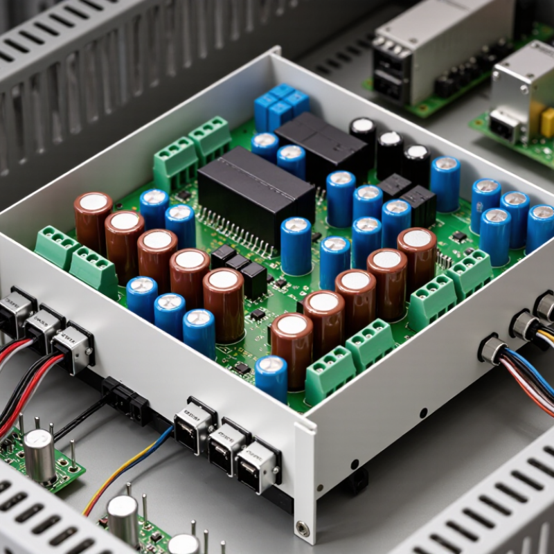
An open-frame DC-DC converter changes one direct-current voltage into another without a protective enclosure. Its circuit board remains visible, with components exposed to surrounding air. The structure usually includes a switching controller, inductors, capacitors, rectifiers, and feedback circuits. Some models also use transformers for electrical isolation. The design can look simple, but it is not.
Its core function is voltage conversion. A higher DC input may become a stable lower output for control boards, sensors, displays, or industrial equipment.
During practical bench testing, engineers check output voltage, ripple, load response, temperature, and startup behavior. Airflow matters because exposed components can cool effectively, yet dust and accidental contact create real concerns. Mounting space must also prevent conductive objects from touching the board.
A common mistake is judging performance from output voltage alone. Efficiency may fall sharply near maximum load. Even experienced designers can overlook heat around inductors or switching devices. That oversight deserves review.
Tips: Confirm the input range and load current first. Leave clearance around hot components. Use insulation or a protective cover when people may touch the assembly. Check ripple with suitable test equipment, not only a basic multimeter. Read the converter’s installation data carefully, and verify results under normal and worst-case conditions.
An open frame DC-DC converter changes one DC voltage into another without an enclosed housing. Its exposed circuit board needs airflow and careful mounting. In practical designs, switching topologies often achieve 85–95% efficiency, depending on load, input voltage, and temperature.
A buck converter reduces voltage by switching a MOSFET rapidly, then smoothing energy through an inductor and capacitor. A boost converter raises voltage using a similar energy-transfer process. Buck-boost circuits handle input levels above or below the output target. Switching frequency, resistance, diode losses, and magnetic design all affect the final result. Higher frequency can reduce component size, but it may increase heat and electromagnetic noise.
Efficiency is not a fixed promise. A converter rated at 92% may deliver less under light loads or poor ventilation. For example, a 100-watt output at 90% efficiency consumes about 111 watts, leaving 11 watts as heat. That heat needs a path away from the board. Measure it.
Engineers should check output ripple, startup behavior, transient response, and protection features during testing. A small fan can improve temperature performance, but airflow may not match the final installation. I have seen calculations look excellent before wiring resistance and connector losses were included. Real measurements sometimes disagree. That is useful. It shows where the design still needs attention.
An open frame DC-DC converter is a power module without a protective enclosure. Its exposed components improve airflow and simplify installation inside equipment. During bench testing, I have found that airflow changes its temperature quickly. Keep fingers and metal objects away.
The input range shows the voltage the converter can safely accept. A 9–36 V model may support different battery or industrial supply conditions. However, operation near either limit can increase stress and reduce efficiency.
Output power depends on voltage, current, cooling, and ambient temperature. Do not size the unit from the nominal load alone. Leave thermal margin. A 50 W load can behave differently in a sealed cabinet.
Ripple is the unwanted AC variation riding on the DC output. Measure it with short oscilloscope connections, because long probe leads can create false spikes. Probe technique matters. Load changes, wiring resistance, and switching frequency also affect ripple. I still recheck results under light and heavy loads; one test point is not enough.
Isolation separates the input and output circuits electrically. It can reduce ground-loop problems and improve system safety when correctly designed. Check isolation voltage, continuous working voltage, and leakage specifications. These values are not interchangeable. An open frame converter may need added spacing, airflow, and mechanical protection after installation. That assumption needs testing.
What Is an Open Frame DC DC Converter?
An open frame DC DC converter transfers DC power without a sealed enclosure. Its exposed components improve airflow, but they also require careful thermal planning. Temperature performance can determine whether a converter operates reliably or fails early.
A practical design begins with the rated load, input voltage, and surrounding temperature. At −40°C, cold-start behavior and capacitor characteristics deserve attention. At 85°C, available output current usually decreases. This derating protects switching devices, transformers, and rectifiers from excessive junction temperature. Never assume the full nameplate current remains safe at high ambient temperatures.
Heat dissipation depends on power loss, airflow, and thermal resistance. For example, a converter delivering 50 watts at 90% efficiency loses about 5.6 watts as heat. That heat must escape through the PCB, component surfaces, and surrounding air. Leave clearance around hot components. Use wide copper areas beneath suitable thermal pads. Forced airflow can help, but its direction matters. A fan blowing across the board may cool one component while warming another.
In field testing, I would monitor the hottest case point, not only room temperature. A small thermocouple near the switching stage can reveal uncomfortable surprises. The first thermal estimate is rarely perfect. Connector heating, dust, and restricted cabinet airflow can change the result. A modest current margin often proves more valuable than a clever calculation. Thin enclosures still need ventilation. Bear that in mind.
| Ambient Temperature | Recommended Output Power Natural Convection |
Recommended Output Power Airflow at 1 m/s |
Derating vs. 24 W Rating Natural Convection |
Estimated Efficiency | Estimated Heat Loss at Listed Power | Estimated Case Temperature Natural Convection |
Design Status |
|---|---|---|---|---|---|---|---|
| −40°C | 24.0 W | 24.0 W | 100% | 88% | 3.27 W | Approximately 52°C | Full rated load |
| −20°C | 24.0 W | 24.0 W | 100% | 89% | 2.97 W | Approximately 63°C | Full rated load |
| 0°C | 24.0 W | 24.0 W | 100% | 90% | 2.67 W | Approximately 75°C | Full rated load |
| 25°C | 24.0 W | 24.0 W | 100% | 90% | 2.67 W | Approximately 100°C | Full rated load |
| 40°C | 21.0 W | 24.0 W | 88% | 90% | 2.33 W | Approximately 105°C | Moderate derating |
| 50°C | 17.0 W | 24.0 W | 71% | 90% | 1.89 W | Approximately 103°C | Thermal derating |
| 60°C | 14.0 W | 21.0 W | 58% | 90% | 1.56 W | Approximately 104°C | Thermal derating |
| 70°C | 10.5 W | 17.0 W | 44% | 90% | 1.17 W | Approximately 103°C | Significant derating |
| 80°C | 7.5 W | 13.0 W | 31% | 90% | 0.83 W | Approximately 103°C | Significant derating |
| 85°C | 6.5 W | 10.5 W | 27% | 90% | 0.72 W | Approximately 105°C | Maximum design temperature |
| Thermal Design Parameters and Heat-Dissipation Calculation | |||
|---|---|---|---|
| Parameter | Reference Value | Unit | Engineering Meaning |
| Nominal output power | 24 | W | Maximum continuous output under the reference operating conditions. |
| Reference efficiency at rated load | 90 | % | Typical efficiency assumption for estimating converter heat generation. |
| Heat dissipation at 24 W output | 2.67 | W | Calculated as Ploss = Pout × (1/η − 1). |
| Target maximum case temperature | 105 | °C | Design limit used to maintain thermal margin below typical semiconductor junction limits. |
| Estimated thermal resistance, natural convection | Approximately 28 | °C/W | Representative board-level value influenced by copper area, airflow obstruction, and mounting orientation. |
| Estimated thermal resistance, 1 m/s airflow | Approximately 18 | °C/W | Representative value when airflow passes across the converter and surrounding PCB. |
| Estimated case-temperature rise | θ × Ploss | °C | The temperature rise depends on both heat loss and the complete thermal path to ambient air. |
| Recommended PCB copper area | At least 2,000 | mm² | A practical starting point for a 24 W open-frame design; larger copper areas generally reduce thermal resistance. |
| Recommended clearance around hot components | At least 5 | mm | Helps maintain airflow and reduces heat transfer to temperature-sensitive components. |
| Thermal verification method | Thermocouple or IR camera | — | Measure the hottest case location after thermal equilibrium at the maximum expected load. |
An open frame DC DC converter is a power module with an exposed circuit board. It transfers DC voltage without a protective case. This format saves space and supports flexible mounting inside larger equipment. However, the final product must provide suitable barriers against accidental contact, dust, and moisture.
Safety starts with the complete system, not the module alone. IEC 62368-1 uses hazard-based principles for many audio, video, information, and communication products. Designers should check insulation, creepage, clearance, temperature, and accessible energy.
The converter’s datasheet helps, but it cannot replace the end-product evaluation. Small gaps can become serious weaknesses. Mechanical tolerances, mounting screws, and nearby metalwork deserve careful inspection.
EMI control depends heavily on layout. Keep switching loops short. Place input capacitors close to the power pins. Use an appropriate filter, grounding method, and shield strategy when testing reveals noise. A quiet bench result may change inside a metal enclosure. That part is often underestimated.
Load matching also requires more than comparing output voltage and rated current. Check startup behavior, minimum load, transient response, ripple, and thermal derating.
A converter rated for 100 watts may deliver less in a sealed enclosure at elevated temperature. Test the real load, including motors, processors, and capacitive input stages. Perfect selection on paper can still fail in hardware.
It changes one DC voltage into another without a protective enclosure. Its circuit board remains exposed. Components stay visible.
Typical parts include switching controllers, inductors, capacitors, rectifiers, and feedback circuits. Some designs include transformers for isolation.
It can power control boards, sensors, displays, and industrial equipment. A higher DC input may become a stable lower output.
Check output voltage, ripple, load response, temperature, and startup behavior. Test with real equipment, not only an unloaded bench.
Airflow can cool exposed components effectively. Dust and accidental contact remain concerns. Leave space around hot inductors and switching devices.
No. Check input range, load current, efficiency, minimum load, ripple, and transient response. A basic multimeter can miss important ripple.
Evaluate the complete product, not just the module. Review insulation, creepage, clearance, temperature, and accessible energy. Add barriers or a cover where contact is possible.
Keep switching loops short and place input capacitors near power pins. Test filters, grounding, and shielding inside the final enclosure. A quiet bench result may change.
Thermal derating may reduce available power inside a sealed enclosure. Motors, processors, and capacitive inputs can create difficult startup conditions. Paper selection is not enough.
Open Frame DC-DC Converters are compact power-conversion modules that transfer electrical energy from one direct-current voltage level to another without a fully enclosed case. Their open construction supports flexible system integration and easier inspection, while switching topologies regulate voltage efficiently, often achieving approximately 85–95% efficiency when properly designed and loaded. Key selection factors include the allowable input-voltage range, rated output power, voltage ripple, and whether galvanic isolation is required for the application.
Reliable operation also depends on thermal and safety considerations. Designers should evaluate derating across temperatures from −40°C to 85°C, provide adequate airflow or heat dissipation, and avoid exceeding the converter’s thermal limits. EMI filtering, suitable layout, and careful grounding help control conducted and radiated interference. Compliance with IEC 62368-1 may be important for equipment safety, while matching the converter to the load’s startup behavior, transient demand, and steady-state current ensures stable performance and longer service life.