Buying EV On-board DC-DC Converters is not a simple voltage-and-price comparison. These compact units keep the vehicle’s 12-volt or 48-volt systems alive while the traction battery operates at far higher voltage. A weak choice can create heat, electromagnetic interference, slower charging, or repeated low-voltage faults. Sometimes, the smallest box causes the biggest workshop problem.
The International Energy Agency reported that global electric-car sales exceeded 17 million units in 2024, with sales expected to continue rising in 2025. That growth increases demand for reliable power-conversion components. Meanwhile, the U.S. Department of Energy highlights efficiency, thermal management, and system integration as important considerations in electric-drive technologies. These reports do not offer a universal converter specification. That limitation matters. Vehicle architecture, auxiliary loads, isolation requirements, and regional operating conditions can change the correct choice.
Power-electronics authority Dr. Alex Lidow has stated, “Efficiency is the key to everything in power electronics.” His observation fits practical converter selection. Every percentage point affects heat, packaging, and available battery energy. However, efficiency alone is not enough. A converter may look excellent on a laboratory datasheet, yet struggle beside an inverter, onboard charger, or long cable harness. This guide examines seven purchasing tips, including voltage range, continuous output, peak-load behavior, isolation, cooling, communication interfaces, certification, and supplier support. Check the details. Ask for test conditions. Confirm performance at cold starts, high temperatures, and sudden accessory loads. Buyers should also question optimistic marketing claims, because real vehicles are rarely as tidy as the brochure suggests.
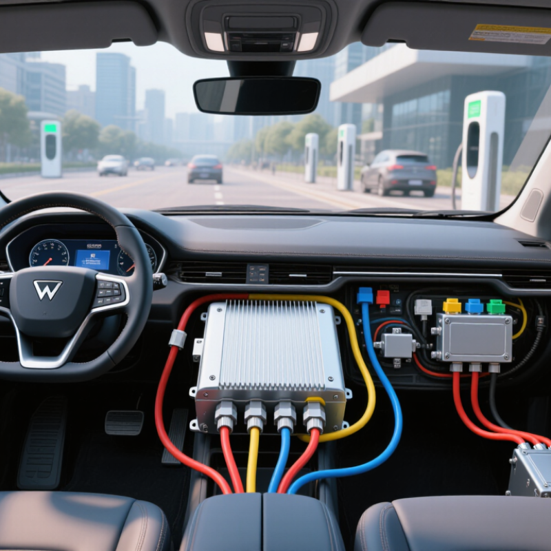
Before buying an EV onboard DC-DC converter, define the vehicle’s real voltage boundaries. A “400 V” system may rise above 450 V during charging or regeneration. An “800 V” platform can also operate across a wide range. Ask for minimum, nominal, and maximum input voltage, not only the system class. This affects insulation, switching stress, efficiency, and protection design. Measure the bus during cold starts and hard acceleration when possible. One test drive is not enough.
Tip: Write the input window clearly, such as 250–500 V or 500–900 V. Confirm continuous and transient ratings separately.
For the output, identify whether the low-voltage network needs 12 V, 24 V, or 48 V. Do not select by voltage alone. Check continuous load, peak current, startup surge, and standby draw. A 12 V system may power control units and lighting, while 48 V loads can demand much higher power. Calculate output power using real duty cycles. A converter rated at 3 kW may not deliver it at high ambient temperatures. Thermal derating is easy to overlook.
Tip: Record charging voltage, allowable ripple, isolation needs, and grounding method. A quiet output matters for sensors and communication equipment.
Experienced integrators compare efficiency at typical loads, not only at full load. Cable length and connector resistance can create surprising voltage drops. Verify short-circuit behavior and service diagnostics before approval. One mistake is assuming every 400-to-12 V converter fits every vehicle. It may not. Ask for test reports, protection thresholds, and clear operating limits. If the specification feels vague, pause and request clarification. That pause can prevent expensive redesigns.
Choosing an EV onboard DC-DC converter starts with matching its 1.5–3 kW rating to the vehicle’s real electrical demand. A 1.5 kW unit may suit basic 12 V loads, lighting, and control systems. Larger battery packs, pumps, cooling fans, and frequent accessory use can justify 2–3 kW capacity. Do not judge by the label alone. Check the continuous output rating at the highest expected temperature, not only the showroom value.
Efficiency above 95% sounds excellent, but the test conditions matter. Ask whether that figure applies at half load, full load, or a narrow voltage range. At 2 kW output, every lost percentage becomes heat that must leave the enclosure. Inspect thermal derating data, cooling requirements, standby consumption, and protection against overvoltage or short circuits. Peak load capacity also deserves careful attention. A converter may handle 3 kW continuously but tolerate 4 kW for only a few seconds. That difference affects compressor starts and sudden fan demand. Check the peak duration and recovery behavior. Real vehicles are uneven. I have seen systems pass steady-load tests yet dip during startup events. This is where specifications can mislead. Leave sensible headroom, but avoid paying for unused capacity. A practical comparison should include output stability, noise, connector quality, service documentation, and verified test conditions. Specification sheets are useful. Independent testing is better.
| Tip | Buying Factor | Recommended Comparison Range | Typical Benchmark | Why It Matters | What to Verify in the Datasheet | Practical Selection Guidance |
|---|---|---|---|---|---|---|
| 1 | Continuous Power Rating | 1.5–3.0 kW | 1.5 kW, 2.0 kW, 2.5 kW, or 3.0 kW continuous output | Continuous power determines whether the converter can supply the vehicle’s normal low-voltage loads without overheating or derating. | Rated output power at the stated ambient temperature, cooling method, input voltage, and mounting orientation. | Select at least 20–30% above the measured continuous load when the vehicle has frequent auxiliary-load changes. |
| 2 | Output Voltage and Current | 12 V or 24 V low-voltage system | 1.5 kW at 12 V ≈ 125 A; 3.0 kW at 12 V ≈ 250 A | Output current affects cable size, fuse selection, connector heating, and voltage drop. | Nominal voltage, adjustable voltage range, maximum continuous current, current limiting, and output ripple. | Match the converter to the vehicle’s battery voltage and confirm that the low-voltage battery and busbars support the required current. |
| 3 | Peak Load Capacity | Short-duration overload capability | Common comparison target: 120–150% of rated power for 5–30 seconds | Short peaks may occur during motorized accessory startup, electric steering support, pumps, fans, or battery recovery events. | Peak power or peak current, duration, repetition interval, thermal conditions, and whether peak operation causes output-voltage reduction. | Do not treat a peak rating as continuous power. Choose a higher continuous rating if high loads persist for minutes rather than seconds. |
| 4 | Conversion Efficiency | >95% preferred | Target: 95–96% at the rated operating point; efficiency may vary with load and input voltage | Higher efficiency reduces heat generation, cooling requirements, and traction-battery energy consumption. | Efficiency curve rather than a single maximum value, including light-load, nominal-load, minimum-input, and maximum-input results. | Compare efficiency at the vehicle’s normal operating load, not only at the manufacturer’s best-case test point. |
| 5 | High-Voltage Input Range | Vehicle-pack dependent | Typical EV converter classes support a wide DC input range, such as 200–450 V or 300–500 V | The converter must remain stable across the battery’s minimum, nominal, maximum, and transient voltage conditions. | Operating input range, absolute maximum input voltage, undervoltage and overvoltage behavior, startup threshold, and shutdown hysteresis. | Use the complete battery voltage window, including charging limits and regenerative events, rather than its nominal voltage alone. |
| 6 | Thermal Management and Derating | Liquid-cooled or forced-air designs | Full rating should be stated at a defined coolant temperature or ambient temperature | Heat reduces efficiency and can cause power derating, shutdown, or reduced service life. | Cooling flow requirement, coolant type, inlet-temperature limit, thermal derating curve, over-temperature protection, and enclosure rating. | Prefer a converter whose full-power test conditions match the vehicle installation environment. |
| 7 | Protection, Isolation, and Compliance | Automotive-grade safety functions | Galvanic isolation, short-circuit protection, overcurrent protection, overvoltage protection, and insulation monitoring compatibility | These functions help protect occupants, the low-voltage network, and the high-voltage battery during faults. | Isolation voltage, insulation resistance, creepage and clearance, ingress protection, EMC test results, reverse-polarity behavior, and applicable vehicle-level requirements. | Require documented test conditions and vehicle-system validation; do not rely on an efficiency figure alone when selecting a high-voltage converter. |
Comparison note: The figures shown are engineering benchmarks for comparing EV on-board DC-DC converter specifications. Actual performance depends on input voltage, output voltage, load profile, cooling conditions, wiring, and vehicle integration. Always confirm final values using the applicable product datasheet and vehicle-level validation results.
An EV on-board DC-DC converter must survive more than a laboratory room temperature. Verify operation from −40°C to 125°C before approving any design. This range may describe the case, baseplate, or semiconductor junction, not the surrounding air. Ask for clear test definitions. A vague temperature rating can hide serious limits.
Thermal performance depends on output power, switching frequency, airflow, and mounting pressure. Check efficiency at low and high battery voltages. Heat rises quickly when the converter supplies continuous auxiliary loads. Inspect derating curves, not only the maximum power number. A converter rated for 3 kW may deliver less near 125°C. Cooling details matter. Forced air, cold plates, and natural convection produce very different results.
During evaluation, mount the unit as it will sit in the vehicle. Use the intended housing, cables, fasteners, and thermal interface material. Place sensors near the hottest case area. Then test repeated temperature cycles, vibration, startup, and maximum load together. One test is not enough. In practical reviews, early thermal estimates are often too optimistic. I would leave margin for blocked vents, dust, aging fans, and imperfect assembly. That margin may reduce usable power, but ignoring it can shorten service life. Also confirm whether protection limits output gradually or shuts the converter down suddenly. The difference affects vehicle control and driver confidence.
When buying an EV onboard DC-DC converter, compliance evidence matters more than a polished datasheet. Request documents before approving samples. For ISO 26262, ask whether the evidence covers the converter, control software, or only development processes. Look for a safety manual, hazard analysis, diagnostic coverage, FMEDA, and clearly stated assumptions of use. An ASIL claim without boundaries is weak. Check required external monitoring, fault reactions, and safe-state timing. These details affect system integration and warranty risk.
CISPR 25 evidence should show the tested configuration, not just a pass statement. Review conducted and radiated emission results, voltage range, load profile, cable length, grounding method, and test class. A converter may pass on a short bench harness yet behave differently in a vehicle. Ask for raw plots and chamber information when possible. Small gaps matter. Switching-frequency changes after thermal tuning can alter emissions, even when output power remains unchanged. Confirm that the report revision matches the offered hardware and firmware.
IATF 16949 evidence should identify the certified manufacturing site and certificate scope. Check validity dates, surveillance status, special-process controls, traceability, and change-notification rules. A certificate alone does not prove stable converter production. Request process capability data for critical solder joints, transformers, connectors, and protection circuits. Review failure-analysis examples and corrective-action records, with sensitive information removed. Be willing to challenge incomplete answers. Excellent test reports can still hide weak production controls. That mismatch deserves a controlled pilot build, extra incoming inspection, and measurable acceptance criteria.
When buying an EV on-board DC-DC converter, inspect its protection features closely. Look for safeguards against overvoltage, undervoltage, overcurrent, short circuits, and excessive temperature. These functions protect the converter and connected vehicle systems during charging faults or unstable loads. Check whether protection resets automatically or requires service intervention. That small detail can affect roadside reliability.
Service life depends on more than a headline efficiency figure. Review thermal design, component ratings, cooling methods, and operation across the vehicle’s voltage range. Ask for test results covering vibration, humidity, salt exposure, temperature cycling, and repeated start-stop events. Real validation data is more useful than general statements. Still, laboratory testing cannot copy every road condition. I would treat optimistic lifetime claims carefully.
Warranty terms reveal how the supplier manages risk. Confirm coverage duration, operating limits, replacement procedures, and exclusions for installation errors. A longer warranty is not always stronger if claims require unclear evidence. Request production traceability, calibration records, and failure-analysis reports from comparable units. These documents support technical confidence and future maintenance planning. Do not overlook service access. A converter may pass testing yet remain difficult to diagnose in the vehicle. That is a practical weakness, and I have seen specifications hide it.
A 1.5 kW unit may support lighting, controls, and basic 12 V loads. Choose 2–3 kW for pumps, cooling fans, larger battery systems, or frequent accessories. Check continuous output at high temperature. Labels can mislead.
Not necessarily. Ask whether testing used half load, full load, or a narrow voltage range. At 2 kW, small losses create noticeable heat inside the enclosure. The test conditions matter.
Check the peak power and its exact duration. A converter might deliver 3 kW continuously but tolerate 4 kW for only several seconds. This affects compressor starts and sudden fan demand. Leave reasonable headroom.
Verify operation from −40°C to 125°C. Confirm whether this range describes the case, baseplate, semiconductor junction, or surrounding air. Those are different conditions. A vague rating hides limits.
Review forced-air, cold-plate, or natural-convection requirements. Inspect derating curves at low and high battery voltages. Test the converter with its actual housing, cables, fasteners, and thermal interface material. Blocked vents and aging fans matter.
Combine maximum load, startup events, vibration, and temperature cycling. Use sensors near the hottest case area. Repeat the tests. One successful run proves little.
Look for overvoltage, undervoltage, overcurrent, short-circuit, and overtemperature protection. Confirm whether recovery is automatic or requires service intervention. That small detail can affect roadside reliability. I might be overly cautious here.
Request data for vibration, humidity, salt exposure, temperature cycling, and repeated start-stop operation. Review warranty duration, operating limits, replacement steps, and exclusions. Check traceability, calibration records, and failure-analysis reports. A long warranty means little when claims are unclear.
Choosing the right EV On-board DC-DC Converters requires more than comparing prices or power ratings. Start by defining the vehicle’s high-voltage input range, typically 400–800 V, and the required low-voltage output of 12, 24, or 48 V. Confirm that the converter can deliver the necessary 1.5–3 kW continuously, achieve efficiency above 95%, and handle short-term peak loads without unstable voltage or excessive heat.
Thermal performance is equally important, especially across temperatures from −40°C to 125°C. Review cooling methods, installation limits, and derating curves before purchase. Buyers should also request evidence of ISO 26262, CISPR 25, and IATF 16949 compliance, along with test reports covering electromagnetic compatibility and functional safety. Finally, evaluate short-circuit, overvoltage, overtemperature, and reverse-polarity protection, as well as expected service life, warranty coverage, and validation data. A careful review of these factors helps ensure reliable operation, easier integration, and long-term value in demanding electric vehicle applications.